Direct answer
A pool equipment system is a circulation and treatment loop. Water leaves through suction outlets, passes through the pump and filter, then through the specified heating and treatment equipment before returning to the pool. Size every component against the same design flow and operating requirements.
Key takeaways
- Size the system around a turnover target and one design flow rate; components chosen in isolation fight each other.
- The pump is the only component that adds energy to the water loop; everything else adds resistance.
- Undersized filters and pipes force pumps to work harder; most equipment problems are hydraulic problems.
- A pool cover reduces heating, chemical and filtration load, which is why it belongs in the equipment conversation.
A pool equipment pad works as a system, not a shopping list. Flow, pressure, treatment requirements and controls link each component, so a change to one item can affect the rest of the loop.
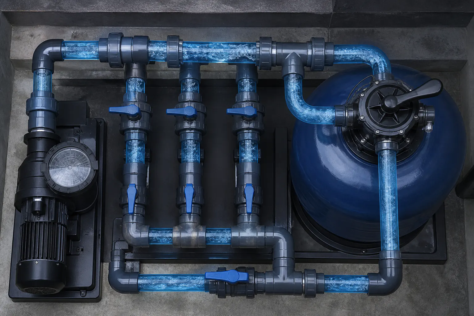
The circulation loop
Pool Shell
   ↓
Skimmers / Suction Outlets
   ↓
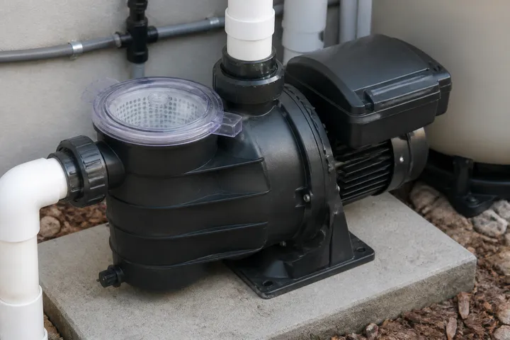
Pump
   ↓
Filter
   ↓
Heating
   ↓
Sanitization
   ↓
Return Inlets
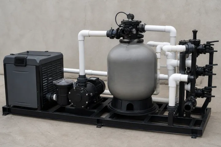
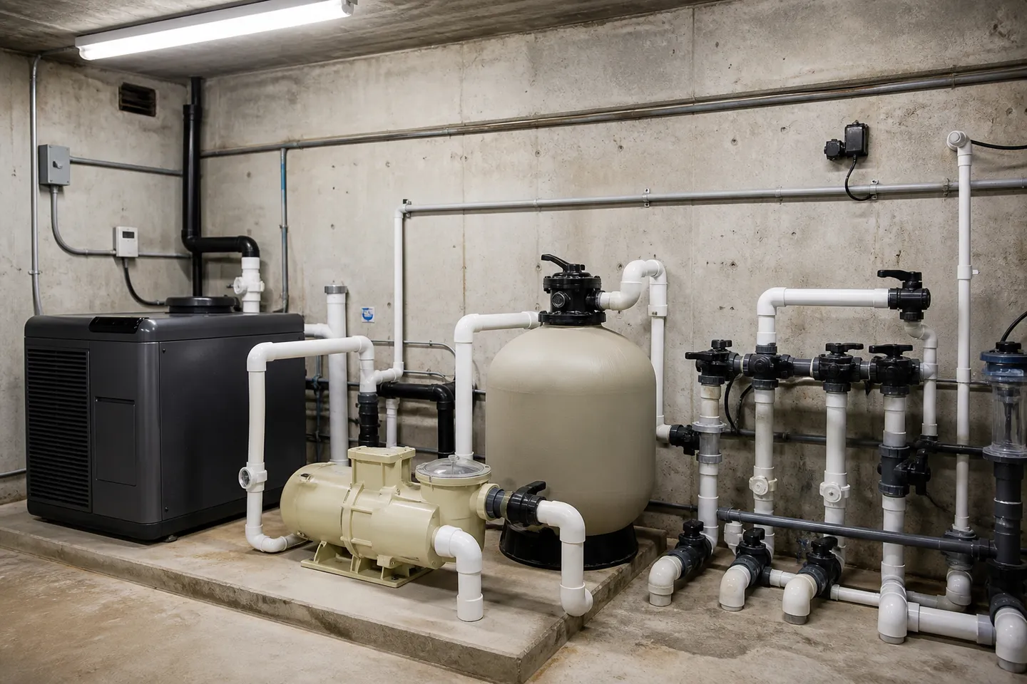
Water leaves through skimmers and other suction outlets, travels to the pump, passes through the filter and the specified heating and treatment equipment, then returns through wall or floor inlets. The precise sequence varies by system. Automation schedules equipment and interlocks; a cover can reduce evaporation, heat loss and debris without sitting in the water path.
One flow rate rules everything
System design starts with the applicable turnover and treatment requirements. Dividing pool volume by turnover time gives a starting flow rate, which is then checked against features, cleaning functions, equipment limits and code requirements:
| Component | Sized by |
|---|---|
| Pump | Design flow at the system’s total head (resistance) |
| Filter | Maximum flux (flow per filter area) at design flow |
| Pipes | Velocity limits at design flow |
| Heater | Volume, desired temperature rise and heat losses |
| Sanitizer | Volume, bather load and climate |
Choose components against different flow assumptions and the mismatch shows up as noise, short filter cycles, poor water clarity or a pump that never reaches its curve. Detailed pump selection is covered in the pool pump sizing guide, and filter choice is covered in pool filter types compared.
Write the basis of design first
The equipment schedule should sit behind a short basis-of-design record. At minimum, record:
- pool volume and the drawing revision used to calculate it;
- the applicable code or owner requirement that sets turnover;
- design flow and any separate flow required by a spa, feature, cleaner or backwash cycle;
- expected operating hours and water-temperature target;
- available electrical service and fuel or heat source;
- pipe material, sizes and the assumed route to the plant area;
- treatment and monitoring requirements;
- outdoor temperature, dust, salt exposure or ventilation conditions that affect equipment placement.
This record makes later changes traceable. If the pool volume, feature flow or equipment-room location changes, the designer can identify which pump, filter, heater, pipe or electrical selection needs to be checked again.
Check every operating mode
One pool can have several operating points. Daily filtration is only the first.
| Mode | Coordination question |
|---|---|
| Daily filtration | Can the pump meet the required circulation flow through the normal treatment path? |
| Heating | Does flow remain within the heater manufacturer’s permitted range? |
| Cleaning | Is there enough flow for the selected cleaner or cleaning circuit without upsetting filtration? |
| Water feature | Is feature flow separate, shared or available only during a scheduled mode? |
| Spa mode | Do valve positions, pump capacity and heater controls match the spa operating sequence? |
| Filter service | Can the filter be cleaned or backwashed using the available flow, waste route and operating procedure? |
Draw these modes on the hydraulic schematic and describe the valve positions or control sequence. Equipment can be individually correct and still fail as a system if two functions compete for the same flow or a control command puts a valve in the wrong position.
The pump adds energy; everything else takes it away
Pipe length, fittings, the filter and the heater all add hydraulic resistance. Lower resistance can let a variable-speed pump meet the required flow at a lower speed. Compare pump curves and ENERGY STAR performance data against the actual system design, then coordinate the layout using the pool equipment room design guide.
Allow for service condition, not only clean catalog condition. A filter accumulates debris, strainers need cleaning and valves add resistance. The selected operating point and control range should accommodate the manufacturer’s stated limits through the normal maintenance cycle. That does not mean adding an arbitrary horsepower margin. It means checking the system curve and each component’s acceptable flow range together.
Where the cover fits
A cover can reduce evaporation, heat loss and debris while the pool is closed. Those effects can change heating loads and operating schedules, so record the automatic pool cover in the equipment schedule and basis of design.
Commercial differences
Commercial and hospitality pools follow stricter codes (faster turnover, redundancy, monitored chemistry; see the CDC’s Model Aquatic Health Code for the U.S. framework) and are planned around downtime avoidance. The commercial planning context is in the hotel and resort pool planning guide.
From overview to procurement
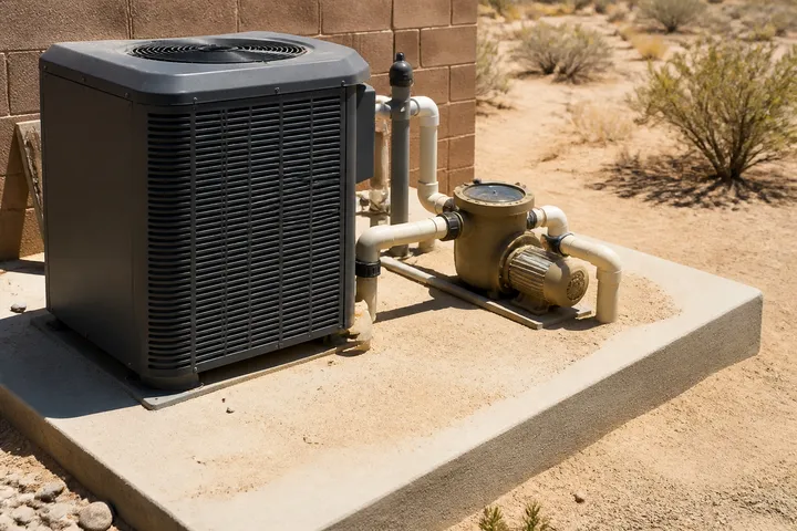
When the loop is understood, the procurement package almost writes itself: one hydraulic schematic, one equipment schedule with shared flow assumptions, and data sheets for each stage. Record the loop on the equipment package checklist before you issue an RFQ. Hot, dusty sites need the extra detailing in pool equipment for hot climates. The Pool Equipment & Automation hub collects the component-level guides.
Commission the loop as a system
Handover should record the final valve positions, pump settings, measured flow where instrumentation is provided, clean-filter pressure, heater and treatment interlocks, alarm behavior and the operating schedule. Confirm that each intended operating mode can be selected and returned to normal filtration without relying on undocumented steps.
Keep the as-built hydraulic and electrical drawings with the equipment schedules and manuals. Future fault finding depends on knowing what was installed and what normal readings looked like at handover. A photograph of an equipment pad is useful, but it is not a substitute for labeled valves, recorded settings and an updated schematic.
Frequently asked questions
What is pool turnover and why does it drive sizing?
Turnover is the time needed to circulate a volume equal to the pool's volume. The required value depends on local code, venue type and the designer's operating basis. It is one input to the design flow used for the pump, filter and piping.
In what order does water pass through the equipment?
A typical loop runs from suction outlets to the pump and filter, then through heating and treatment equipment before the return inlets. Exact order, check valves and injection points must follow the equipment manuals and local code.
Sources
- Pool Pumps — ENERGY STAR Accessed August 23, 2026.
- Model Aquatic Health Code — U.S. Centers for Disease Control and Prevention Accessed August 23, 2026.
- 2025-2026 Pool and Spa Product Catalog — Pentair Accessed August 23, 2026.