Direct answer
Design the pool equipment room around the actual equipment dimensions and service clearances. Include drainage, ventilation, code-compliant electrical provisions and any required separated chemical storage, while keeping pipe runs practical for the site.
Key takeaways
- Size the room around the real equipment schedule plus service clearances, not around leftover floor plan.
- Short pipe runs between pool and room reduce head, energy cost and noise for the system's entire life.
- Ventilation, floor drainage and separated chemical storage are requirements, not upgrades.
- Every serviceable component needs reach and sightlines; a room you cannot work in becomes a room that is not maintained.
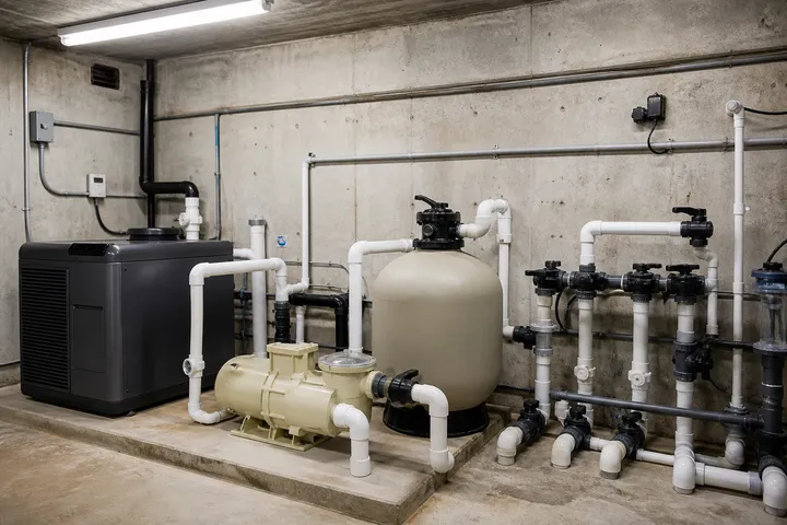
The equipment room contains most of the circulation loop and provides access for routine service. Its layout should come from the actual equipment schedule, pipe routes and maintenance tasks.
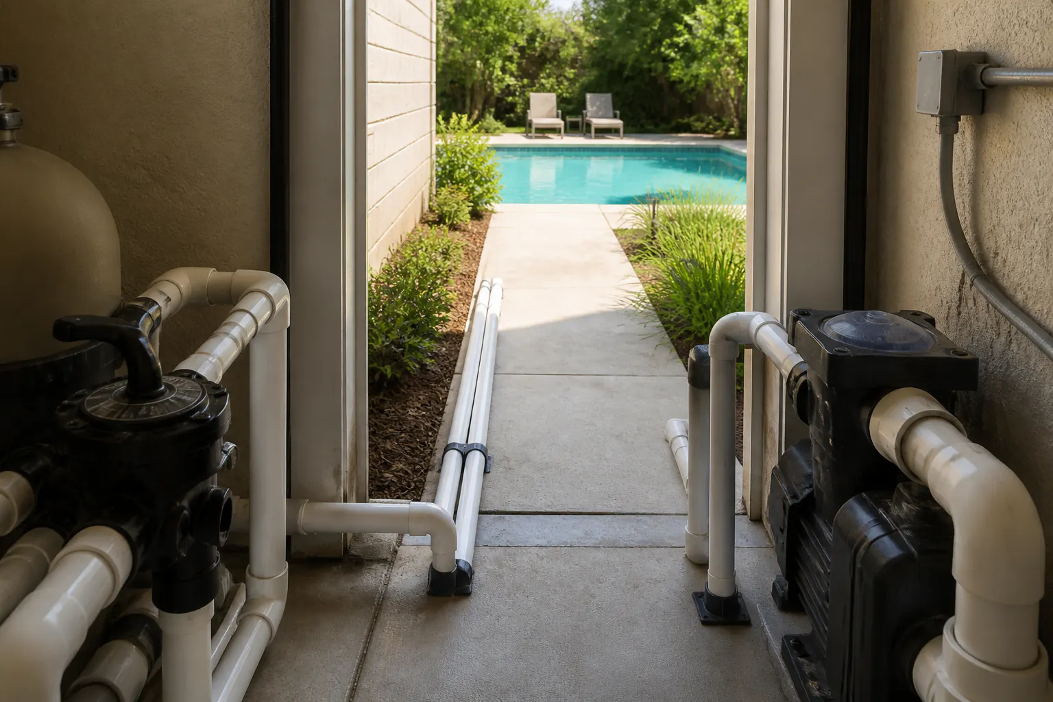
Location: short pipes win
Shorter suction and return routes reduce the pipe resistance included in the system head. When the site requires a longer route, the designer should check pipe diameter and pump selection using the pump sizing guide.
Noise and access may push the room away from bedrooms, terraces or guest areas. Put the hydraulic route, service route and nearby occupied spaces on the same site plan before selecting the location.
Plan the route into the room
Check how each major item reaches its final position. The door, corridor, steps and turning space must suit the equipment dimensions and the daily operator. Leave a route for a pump, filter component or heater to be removed without dismantling unrelated pipework.
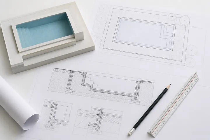
The same review applies overhead. Filter lids, cartridge stacks, valves and cable trays can compete for vertical space. A section drawing often catches conflicts that a floor plan misses.
Space: schedule plus clearances
Size the room from the actual equipment schedule:
| Item | Space consideration |
|---|---|
| Pump(s) | Access to strainer basket without dismantling pipe |
| Filter | Full clearance above (cartridge withdrawal) or beside (sand media loading) |
| Heater / heat pump | Manufacturer clearances; heat pumps need airflow or ducting |
| Sanitization / dosing | Eye-level mounting, calibration access |
| Automation panel | Readable, reachable, away from splash |
| Manifolds and valves | Labeled, operable without reaching across equipment |
A useful design check is to take each maintenance task from the manufacturer’s manual and mark the working area on the plan. If one task requires moving another component, revise the layout before the pipework is fixed.
Keep gauges, valve labels and control screens visible from a safe standing position. Avoid placing routine service points behind hot equipment or across a chemical-storage area.
Ventilation, drainage, chemicals
Ventilation must meet the equipment and chemical-storage requirements used for the project. Heat pumps and other air-moving equipment need their documented airflow clearances.
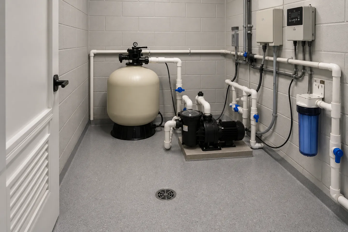
Show the floor drainage route and finished falls on the drawing. Backwash, filter service and ordinary leaks all put water on the floor. The drain should not rely on an operator setting up a temporary hose during an incident.
Chemical storage must follow the applicable code, safety data sheets and CDC guidance. Identify incompatible products, ventilation, spill provisions and access control in the room plan. Do not place a generic chemical shelf beside an electrical panel and treat the issue as resolved.
Coordinate pipework before installation
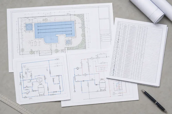
Draw the suction and return manifolds, isolation valves, check valves and waste route at a scale that shows access. Label the normal flow direction and leave room to operate valve handles. Where pipes cross, use a section or elevation so the installer does not have to choose the order on site.
Place unions or other service connections where equipment can be removed according to its manual. The final pipe layout should not block the filter lid, pump basket or heater panel.
Electrical and controls
Provide code-compliant protection (GFCI/RCD), bonding and dedicated circuits sized for the full schedule, including planned future items. Conduits for pool lighting and a future cover housing are easier to place during construction than after the deck is finished.
Commercial plant rooms
Commercial rooms add redundancy (duty/standby pumps), chemical monitoring, and staff access requirements; they are planned as part of operations, not construction; context in the hotel and resort pool planning guide.
The operating team should review alarm access, chemical delivery, spare-parts storage and the route used during a breakdown. These are different from the contractor’s installation route and may be needed while the property remains open.
On the checklist
Room location, dimensions, ventilation, drainage and electrical provisions all belong on the drawings before excavation; they are Stage 3 of the new pool planning checklist.
At handover, keep an as-built layout, valve schedule, electrical information and the initial commissioning readings in the room or the site’s document system. Photographing the completed room helps, but labels and updated drawings are what a later technician can use.
Frequently asked questions
How far can the equipment room be from the pool?
There is no single limit, but every added meter of pipe adds head the pump must overcome. Keep runs as short as the site allows and increase pipe diameter when distance is unavoidable.
Can pool chemicals be stored in the equipment room?
Follow local code and each product's safety data sheet. CDC guidance recommends dedicated chemical storage separated from equipment where possible, with incompatible products isolated and suitable ventilation and access controls.
Sources
- Model Aquatic Health Code — U.S. Centers for Disease Control and Prevention Accessed August 23, 2026.
- Pool Chemical Safety — U.S. Centers for Disease Control and Prevention Accessed August 23, 2026.
- Pool Pumps — ENERGY STAR Accessed August 23, 2026.