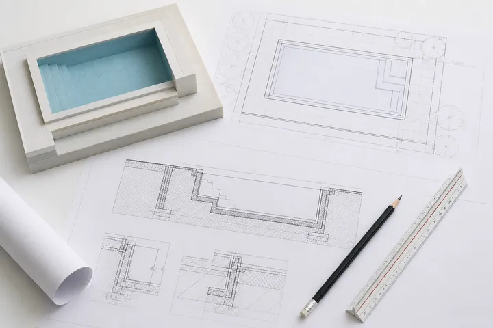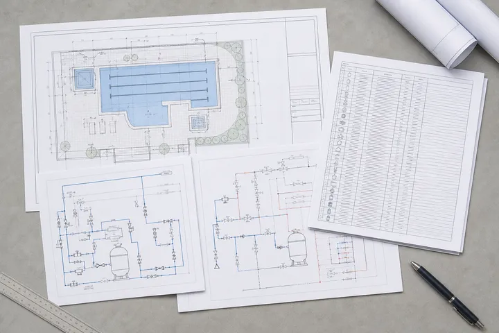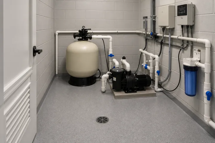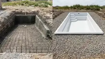
Match the inground pool shell to the site soil profile and backyard access corridor during pool planning.
The versatility of shotcrete placement allows for the construction of a concrete pool shell of virtually any size and shape.
The Latham Coral 16 fiberglass pool has outer dimensions of 30’ 10” x 16’, a depth of 3’ 6” to 6’ 11”, and a capacity of 9,000 gallons.
Scroll horizontally to see all columns when the table extends beyond the screen.
Gunite Pool Construction, Reinforcement, and Curing Specifications
Evaluating gunite pool vs fiberglass structural performance begins with how pneumatically projected concrete mixtures, steel reinforcing grids, and hydration curing schedules establish a monolithic basin when compiling a new pool planning checklist.
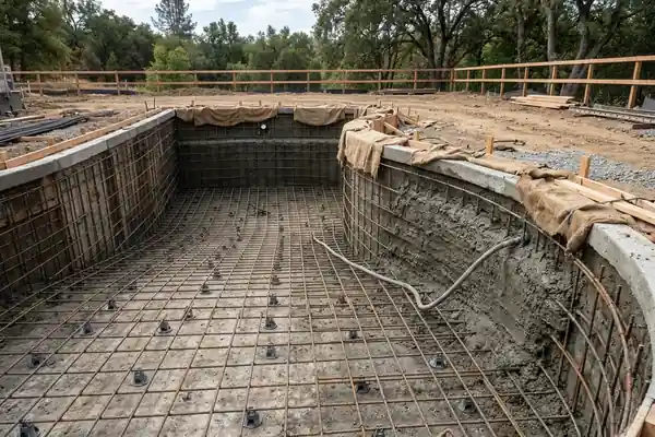
For gunite pool construction, paste coverage, water-cementitious ratio, and air compressor output govern shell density and watertightness.
Special attention should be given to the amount of fine aggregate and cementitious paste necessary to cover the aggregate surface area (minimum 4:1 cementitious-to-aggregate ratio, and ideally 3:1).
Concrete intended to have low permeability when exposed to water should have a maximum w/cm of 0.45 with a minimum 4000 psi compressive strength.
When the concrete is exposed to chlorides (brackish water, salts, and seawater), ACI 350 requires a maximum w/cm of 0.40 and compressive values of 5000 psi (34 MPa) to provide protection for embedded reinforcement.
The shotcrete contractor should use an air compressor able to produce at least 385 CFM (11 m3/min) of air flow at 120 psi (0.83 MPa).
When placing shotcrete onto an existing concrete surface, the surface should be roughened and clean with a roughness amplitude of +/- 1/16th in. (1.6 mm) or more.
ASA recommends a minimum of 7 days curing to help control shrinkage issues in young concrete sections.
ASTM C1604 gives guidance on taking drilled cores of shotcrete from existing structures, and a minimum 3” diameter core is recommended.
Grout samples of the gunite should be tested for compressive strength in accordance with ASTM C42, obtaining at least four grout samples from each 400 sq. ft. of pool footprint or 50 cubic yards placed.
Reinforcing bar diameter and center-to-center grid spacing resist flexural soil and water loads across custom shell spans.
In swimming pools, No. 4 (No. 13M) reinforcing bar is the minimum size bar that should be used.
Depending on the design, many pools use No. 5 bars (No. 16M) and No. 6 bars (No. 19M) in the reinforcing steel layout to strengthen the concrete due to higher loadings.
Typically, pools use a minimum of reinforcing bars spaced at 12 in. on center each way, while many projects call for 8 or 6 in. (200 or 150 mm) spacing.
Geotechnical Site Investigation, Expansive Clay Movement, and Hydrostatic Uplift
A geotechnical study should be conducted to address slope stability and erosion for pools designed and constructed on slopes steeper than 5(h):1 (v).
In general, the depth of the soil borings for a pool should be twice the depth of the pool with a minimum depth of 20-ft.
Expansive soils are classified to be soils with liquid limit greater than 40 and plasticity index (PI) of greater than 20.
When expansive clay is excavated beneath the shell footprint, engineered replacement fill and moisture control limit differential soil swell.
Select structural fill consists of lean clays with liquid limit of less than 40 and plasticity index between 12 and 20.
All the select structural fill in the pool area should be compacted to a minimum of 95% standard proctor density (ASTM D698) at ±2% of optimum moisture.
A vertical moisture barrier can be placed next to pool coping and should extend deep enough to reduce soil suction changes, which may be about six- to seven-ft deep.
The pool structure can also be supported on a helical pile system founded below a depth of 15-ft.
High groundwater levels also exert upward buoyancy forces on an empty or partially drained basin.
For buoyancy design, the pool structure should perform satisfactorily if a design factor of safety against uplift of 2.0 is used, and should be assumed empty unless the design includes a means of relieving external hydrostatic forces during pool maintenance.
The submerged soil unit weight of 60 pound per cubic foot (pcf) can be used to compute soil resistance to uplift loads, and a dry unit weight of 150 pcf should be used for gunite and reinforcing.
The Hayward SP1056 Hydrostatic Relief Valve is to be used with the internal 1 1/2” NPT or 2” NPT in a sump along with the SP1055 Slotted Collector tube on the bottom of the sump.
At least one hydrostatic relief valve in a set of suction outlets will allow hydrostatic uplift pressure caused by ground water to be relieved into the pool or spa.
Scroll horizontally to see all columns when the table extends beyond the screen.
Fiberglass Shell Envelopes, Rigging, Backfill Balance, and Service Restrictions
Factory-molded composite shells arrive on site as one-piece vessels with defined molding tolerances, rigging rules, gravel backfill specs, and water-level restrictions that must be verified on a pool drawings and bill of materials checklist.
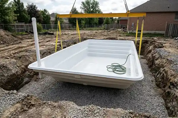
Published shell dimensions include top-beam extensions and normal composite molding variations across manufacturers.
For Thursday Pools fiberglass shells, actual lengths, widths, and depths may vary by approximately 2-3% due to rounding and normal manufacturing tolerances, and actual dimensions of the delivered pool shell govern.
For Fiber Pools Prime fiberglass shells, the pool beam typically extends 4 to 7 inches beyond the waterline on all sides, and overall length and width dimensions may vary by up to 4%.
The coping of a Latham fiberglass pool is approximately 4” to 6” on all sides, with a general difference of 8” to 12” between installation guide dimensions and water’s-edge permit plans.
Excavation setbacks, trench drainage, and crane rigging follow strict dimensional clearances.
For a Rainforest Pools installation, for every foot of pool depth the pool should be a minimum of plus one foot off any foundations, and 12’ access from the front of the property to the backyard is ideal.
The excavation clearance around the Latham fiberglass pool shell is approximately 6” on the sides and 6” on the ends, and the bottom of the excavation is over-dug approximately 4”.
Per Latham, never use excavated material as fill or backfill in the hole; the material will settle; in significant over-excavation or seasonal high water areas, you may want to mix 10% Portland cement with the backfill for stabilization.
Latham requires a permanent sump pipe (or gravity-fed daylight drain) on all pools, suggesting an 18” x 8’ x 18” trench across the deep end with a 3” perforated PVC pipe connected to a vertical 8” PVC standpipe.
Latham recommends lifting all fiberglass pool models over 12’ wide with a spreader bar and 20’ lifting straps.
Per Latham, the fiberglass pool can be separated from the lifting equipment when the entire perimeter of the pool (including all transitions) is within 1/2” of level with tile preinstalled, or 1” of level if tile is to be installed later.
For Latham fiberglass pools, After approximately 12” of water is in the fiberglass pool and backfill has been placed evenly, the backfill and water should always be +/- 6” of each other.
Per Latham, the walls of the pool may bulge inward if too much backfill has preceded the water in the pool, or outward if too much water precedes the backfill.
The Latham fiberglass pool does not require annual draining for service, and damage caused due to the water being drained below the level of the skimmer inlet is specifically excluded from the Latham warranty.
Pool Coping Stones, Perimeter Bond Beams, and Deck Expansion Joints
Detailing pool coping stones, perimeter bond beams, and foam-backed sealant joints isolates the shell edge from deck movement during initial construction or a later pool renovation planning guide project.
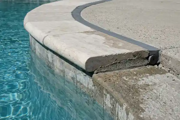
Composite shells anchor into perimeter concrete beams and collars differently than monolithic concrete pool walls.
Per Latham, half-inch holes may be drilled into the lip of the pool every 3’, with two-foot lengths of 3/8” rebar placed in each hole and bent at 90 degree angles to anchor the sides of the pool.
For Unilock pool coping, the maximum recommended length on straight walls is 72” (1.8m), while radius pools should avoid coping units longer than 18” (45cm).
Unilock pool coping should overhang approximately 2” (50mm) and slope at a 2% grade away from the pool.
Techo-Bloc Pacific pool coping cross-sections specify a 1/2’’ foam backer rod and self-leveling caulk at the joint, with a concrete deck minimum of 39” (1 m) wide by 4” (100 mm) thick.
Scroll horizontally to see all columns when the table extends beyond the screen.
Sources
- American Shotcrete Association - Position Statement on Watertight Shotcrete for Swimming Pools
- American Shotcrete Association - Pool Portal Technical FAQs and Shotcrete Magazine Reinforcement Guidance
- Geotech Engineering and Testing - Recommended Guidelines for Design and Construction of Inground Swimming Pools
- Latham Pool Products - Coral Fiberglass Pool Specifications and Fiberglass Pool Installation Guide
- Thursday Pools - Fiberglass Pool Care Guide
- Rainforest Pools and Composites - Master Installation Guide
- Fiber Pools and Spas - Prime Fiberglass Pool Installation Guide
- Hayward Pool Products - Hydrostatic Relief Valve and Dual Submerged Suction Outlet Manuals
- Unilock - How-To Install Pool Coping Guide
- Techo-Bloc - Pool Copings Brochure and Installation Details
Sources
- Anglo American Pools Pool Planning Guide — Anglo American Pools Accessed October 28, 2026.