Automatic Pool Cover Repair Diagnostics: Travel Skew and Track Alignment
When a Coverstar cover does not start out evenly after it is pulled all the way off the pool and then pulled out approximately one foot, adjust the rope length on the side that is lagging.
When diagnosing a Coverstar cover that does not run square, check if the sliders are binding, if the track is clear of sand or mud, if the track is bent, or if a slider is tilted at an angle causing binding.
For a Coverstar cover that has never run square, verify that the distance from the end of the track to the center of the rollup tube on the motor end equals that on the non-motor end, and that track width is equal at the mechanism, center, and shallow end.
On Coverstar undertrack and recessed top track systems that do not run square, inspect whether the cover is rubbing against the box, the non-motor rope is catching under a lid bracket, or the cover is wearing the plastic guide feeds unevenly.
On Cover-Pools Universal Track Systems, run the cover to within two to three inches of the end of the track when closing and do not close the cover completely against the pulley castings at the end of the tracks.
On Cover-Pools automatic pool covers, a track end pulley usually lasts about three years, and a noticeable clicking or grinding sound from the end of the track indicates a worn pulley that can cause adjustment problems and a broken rope.
On Cover-Pools mechanisms, never apply grease or silicone to the rope, webbing, or tracks because it will cause rapid deterioration of the threads, fabric, and track.
On a Cover-Pools system with non-locked rope reels, uneven cover retraction is corrected by tightening the brake wing nut clockwise on the side that consistently comes back first, or loosening the brake on the slowest side while leaving a little brake on both sides.
On an Aquamatic HydraMatic Compact system, skew alignment is adjusted with the cover fully closed by loosening the two 9/16 Hex Head Bolts on the drive unit by two complete revolutions and inserting a screwdriver into the pre-cut slots to adjust the roller tube.
Scroll horizontally to see all columns when the table extends beyond the screen.
Drive Rope Adjustment, Webbing Splice Repair, and Slider Replacement
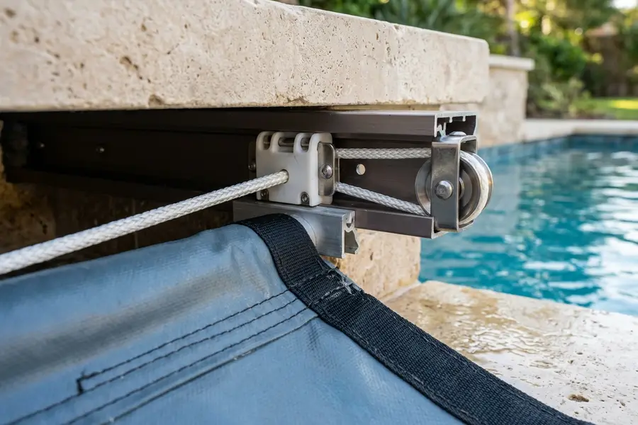
During a Coverstar rope adjustment, pull both sides of the leading edge approximately 6” into the tracks, pull all slack out, and mark and cut the ropes so a minimum of 8’ of rope remains to wrap around the rope reel.
On Coverstar rope adjustments, it is acceptable if the non-motor end starts slightly ahead of the motor end, provided it is not more than 1” ahead to allow the non-motor end rope to stretch slightly.
On older aluminum Coverstar systems, never use a screw longer than 1/2” to attach the rope to the rope reel, as longer screws can prevent the cover from running properly.
When repairing a broken rope with a pre-sewn webbing splice on a Pool Cover Specialists cover, use a utility knife to pick out the stitches joining the fabric to the webbing for a distance equal to the webbing splice minus two inches.
In Pool Cover Specialists broken rope repair, cut around the beaded portion of the webbing so the rope end protrudes an inch beyond the severed webbing, and burn both the cover rope-end and splice rope-end.
When overlapping webbing during a Pool Cover Specialists rope splice repair, the new splice webbing must overlap the existing cover webbing; if old webbing overlaps new webbing, the splice will catch in the track and tear the webbing.
When finishing a Pool Cover Specialists rope splice repair at the front corner stress point, stitch back and forth for six or seven stitches with the sewing awl to reinforce the webbing-to-fabric bond.
Replacing a damaged PCS Universal Slider (Part ID# 22049) requires a 1/8” Allen wrench or Phillips screwdriver and a 1/2” wrench, starting with the pool cover in the fully Open position to locate and release the Cover Guide from the track end.
During PCS slider replacement, with the cover in the Open position, unscrew the Auto-stop Sensor from the Guide, use a 1/8” Allen wrench or Phillips screwdriver to remove the upper screw on the Guide, pull about one foot of slack rope to remove the broken slider, and use a 1/2” wrench to detach the black plastic slider from the Leading Edge Assembly.
When removing undertrack shims to install a replacement rope in a Pool Cover Specialists undertrack system, remove the last ten feet of shims on the end of the tracks away from the mechanism to pull the track out and access the pulley housing.
Torque Limiter, Slip Clutch, and Limit Control Sensor Calibration
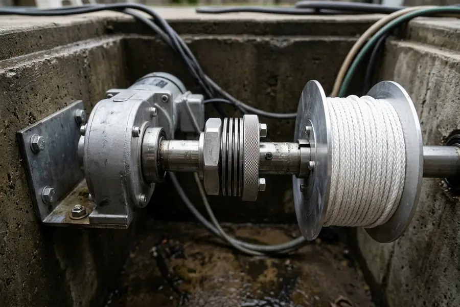
On a Pool Cover Specialists system, if the cover stops halfway when opening or closing, check for debris inside the track, ropes tangled around the rope reel, water that has not been pumped off the pool cover, or the cover sticking to the deck.
On a Pool Cover Specialists system, rough and jerking cover travel is caused by webbing catching on the guide, the cover sticking to the deck, overly tight rope reel tension, track debris, broken sliders, housing debris, splice catching, or pulleys locking up.
To adjust a Coverstar torque limiter, use two 1/2” wrenches to tighten one side approximately 1/2 turn, then rotate the torque limiter 180 degrees and tighten the opposite side the same amount.
When adjusting a Coverstar torque limiter, the gap between the nylon blocks on each side should be equal or the mechanism may not shift properly; if the torque limiter has slipped excessively with melted nylon around the center disk, sand the nylon blocks and center disk.
To adjust a Cover-Pools slip clutch when the cover pauses mid-travel, use a 1/2” socket, 6” socket extension, and ratchet handle to turn both adjustment nuts equally in 1/8 turn increments after verifying no track debris, water on the cover, or bad pulleys exist.
On Cover-Pools systems equipped with an Auto-Shutoff Amp Limiter board, the board senses motor amperage draw and shuts off the motor if the cover hits an obstacle or resistance during the cover or uncover cycle.
The Coverstar Micro-Rotary Limit Switch mounts on the non-motor side of the roll-up tube with a trigger disc; exact positioning of the cover can vary up to 1 foot due to how the cover rolls up, and it is powered by two AA lithium batteries lasting over 10 years.
The Coverstar Micro-Rotary Limit Switch includes 30’ 18/4 AWG 300V wire and is rated for a maximum switching power of 60W (125VA), 220VDC / 250VAC, and 2 AMPS.
To set the Home position on the Coverstar Micro-Rotary Limit Switch, position the cover where you want the feature to turn on (typically about a foot in front of the cover open position), press the top button so the LED blinks 3 times, and operate the cover in the closing direction for at least 5 feet.
The Coverstar motor limit control requires 8 amps for the motor, uses a 15amp GFCI breaker at the panel, must have its enclosure mounted as high as possible in the cover box, and is not designed to work with five-wire motors.
When testing a Coverstar limit sensor while the cover is running in the close direction, if a Hall Effect Sensor does not stop the cover, flip the polarity-sensitive magnet; if a reed switch does not stop the cover, switch the S1 and S2 leads.
Scroll horizontally to see all columns when the table extends beyond the screen.
Automatic Pool Cover Motor Replacement and Hydraulic Power Pack Diagnostics
On a Pool Cover Specialists system, if the cover is completely closed, will not open, and makes a noise, the fault is a locked-up motor, gear or bearing issue, bad control board, broken drive pin, sheared clutch screws, or dogs not engaging.
On a Pool Cover Specialists Infinity 4000 mechanism, if the Double Dog / Main Shaft Assembly requires replacement, isolate and replace the entire Double Dog / Main Shaft Assembly, and use an Allen wrench to remove the single dog gear from the end-casting and from the rope reel.
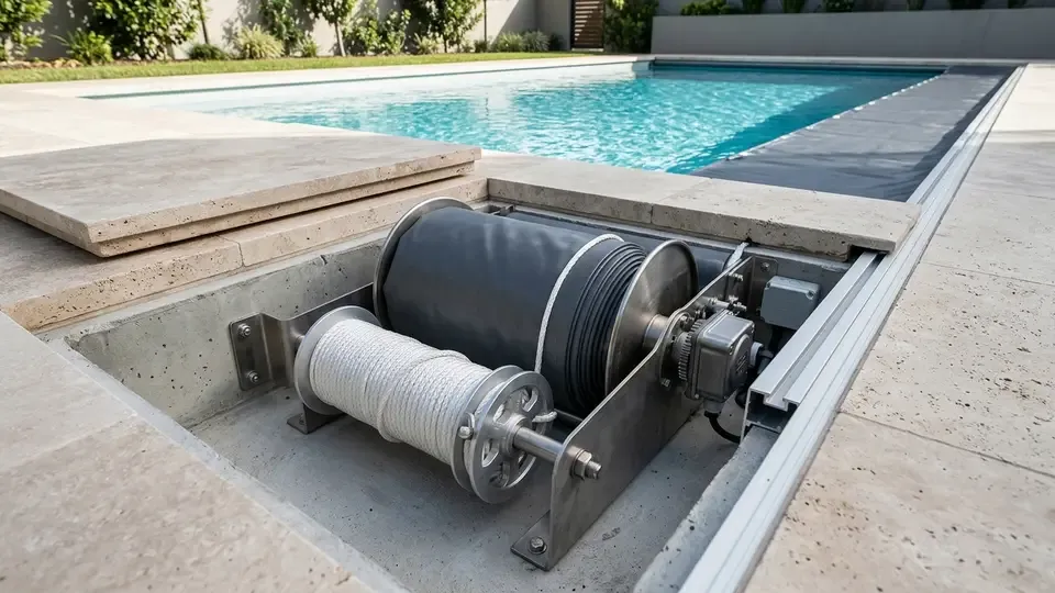
To manually uncover a Cover-Pools pool cover in an emergency, remove the coupler or slip clutch bolt, loosen both brakes completely, and insert a 1/2” drive ratchet socket wrench into square hole washer #110145 on the opposite end of the mechanism to reverse the main tube.
On a Cover-Pools Save-T 3 mechanism, lubricate the Opposite End Bearing (#110003) and Motor Side End Hub (#110427) twice per season using waterproof lithium grease (Lubriplate #1200-2).
On a Cover-Pools system with a hydraulic drive, check the hydraulic tank fluid twice per season using Automatic Transmission Fluid (ATF) Type “F” or Dextron III, and drain, flush, and refill the tank, motor, and lines once per year.
Electrical wiring to the Latham hydraulic power pack requires a breaker disconnect: a 20 amp 220V GFCI breaker for U.S. installations or a 20 amp 230V breaker for European installations.
The Latham hydraulic power pack tank requires approximately 3 quarts of oil plus approximately 1 pint of fluid for each additional 10 feet of hydraulic hose run.
The Latham hydraulic unit has one bypass valve located on the side of the power pack covered by a cap that is removed with a 7/8” wrench, and the valve is preset at the factory to 600 pounds pressure.
To adjust the Latham hydraulic bypass valve, use a 7/8” wrench to loosen the top bypass cap and use a #3 flat head screwdriver to turn the pressure relief screw counter-clockwise until the cover stalls, then clockwise in small increments until the cover runs smoothly.
On the Latham hydraulic power pack, hydraulic fluid must be replaced every 12 - 24 months to remove contamination, or sooner if the fluid takes on a dark color, foul smell, or milky/cloudy appearance.
If the Latham hydraulic power pack has no power or reduced power, purge bypass valve contamination by loosening the bypass screw counter-clockwise (leaving at least 3 full turns in the threaded hole), running the power pack for 30 seconds, and readjusting; also verify voltage does not drop more than 5% while running.
If the Latham hydraulic power pack only works in one direction, test the solenoid coil by removing the 3/4 inch nut holding the coil to the valve assembly, placing a plastic-handle screwdriver inside the coil, and running the system in both directions to verify the screwdriver magnetizes in one direction.
Aquamatic HydraMatic Compact hydraulic drive systems use 3/8 inch I.D. hydraulic hose rated for a working pressure of 1250 to 2250 psi with #6-JIC 37 female swivel fittings.
On an Aquamatic HydraMatic Compact drive unit, RIGHT HAND drive units connect hydraulic hoses from “A” on the torque motor to “1” on the manifold and “B” to “4”, whereas LEFT HAND drive units connect “A” to “4” and “B” to “1”.
The Aquamatic HydraMatic Compact power-pack reservoir holds 3 1/2 quarts of Dexron III Automatic Transmission Fluid or regular hydraulic fluid, plus an additional one-quart per 35 ft. of hydraulic hose.
To increase hydraulic operating pressure on an Aquamatic HydraMatic Compact power-pack if the cover hesitates, loosen the pressure relief valve jam nut with a 9/16” socket and turn the set screw clockwise with a 3/16” Allen wrench.
Scroll horizontally to see all columns when the table extends beyond the screen.
Automatic Pool Cover Replacement Fabric and Roll-Up Tube Pinning
On Pool Cover Specialists systems, approximately 1% shrinkage naturally occurs over the life of the pool cover fabric, while a popping sound under tension is normal when ropes drop off the high side of the rope reel.
Cover-Pools vinyl cover fabric shrinks between one to two percent over time, which equals three to four inches on a 20-foot wide pool cover, and indoor pools may shrink more because they are often heated year-round.
When unrolling a Pool Cover Specialists replacement cover about two feet behind the tracks, all seams on the cover face downward and manufacturer warning labels always face upwards.
On a Pool Cover Specialists replacement cover, when sewing old and new ropes together to pull a replacement cover rope through the track, each rope end must be burned or fused down to a diameter less than the rope so it passes through the end pulley without breaking the thread.
On a Pool Cover Specialists replacement cover, with the cover in the open position, hold both ropes even, mark and cut them approximately 4 - 5 feet from where they leave the rope reel, and fuse the cut ends.
To pin the ropes on a Pool Cover Specialists replacement cover, insert a #10 x 5/8” screw through the ropes 3” from the rope end and into the pre-drilled holes in the rope reel.
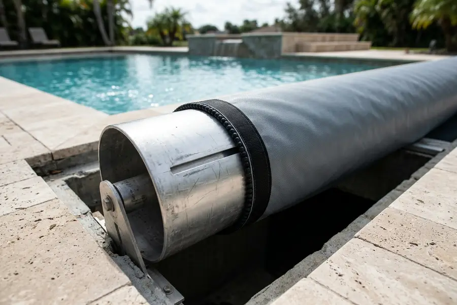
To pin a Pool Cover Specialists replacement cover fabric to the roll-up tube, use an 11/64” drill bit to drill 5 evenly spaced holes in a straight line across the roll-up tube, starting approximately 2 1/2 inches from each end.
When pinning Pool Cover Specialists replacement fabric to the roll-up tube, pull the fabric tail six inches beyond the outer holes and pin both ends with #10 x 1/2” or self-tapping screws, then pull the center one inch beyond the center hole and pin.
Sources
- Latham Pool Products - Coverstar Cover Does Not Run Square Service Guide.
- Latham Pool Products - Coverstar Rope Adjustment Service Instructions.
- Latham Pool Products - Coverstar Torque Limiter Adjustment Manual.
- Latham Pool Products - Coverstar Micro-Rotary Encoder Limit Switch Guide.
- Latham Pool Products - Coverstar Motor Limit Control Installation Instructions.
- Latham Pool Products - Hydraulic Pump Installation and Troubleshooting Instructions.
- Pool Cover Specialists - Automatic Pool Cover Common Concerns and Troubleshooting Guide.
- Pool Cover Specialists - Repairing a Broken Rope Service Guide.
- Pool Cover Specialists - Replacing a Damaged Universal Slider Service Guide.
- Pool Cover Specialists - Replacement Cover Fabric Installation Instructions.
- Pool Cover Specialists - Replacing the Infinity 4000 Gear System Service Manual.
- Cover-Pools - Automatic Pool Cover Owner and Maintenance Manuals.
- Aquamatic Cover Systems - HydraMatic Compact Pool Cover Installation Manual.
Sources
- Anglo American Pools Automatic Pool Covers Guide — Anglo American Pools Accessed October 28, 2026.